Introduction to CAN Bus (Controller Area Network Bus)
The Controller Area Network (CAN) bus is a revolutionary communication protocol that has taken vehicle electronics to a whole new level. Developed by Robert Bosch in the 1980s, CAN bus technology integrates various electronic components in a vehicle and establishes neural communication between them.
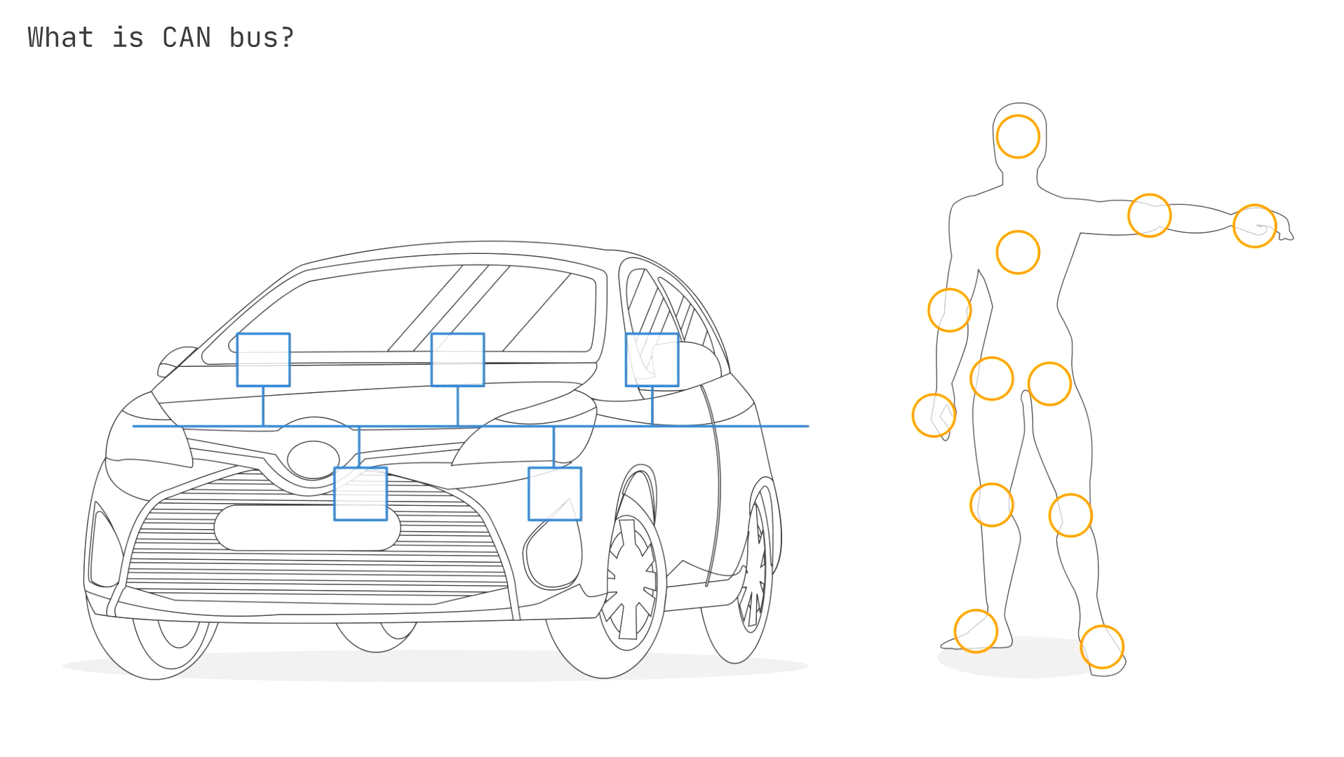
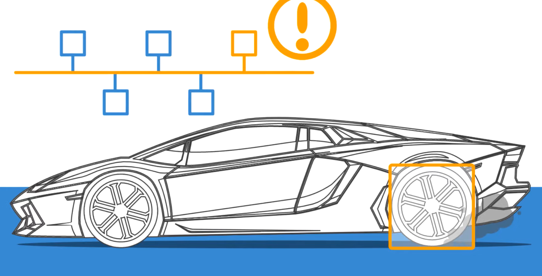
In short, it acts like a nervous system in the human body that keeps different organisms interconnected. Only in this case are the ECUs (Electronic Control Units) connected. What’s more? A can bus system doesn’t even need a central computer or control systems. Its design ensures reliable, real-time data exchange.
So, if you’re looking to enhance your vehicle’s lighting system, CAN bus ECUs (Electronic Control Units) for LEDs can be a smart solution. These units can integrate with the existing CAN bus network to give you access to intelligent control and monitoring of LED lighting.
Let’s delve deeper into the topics and find out if it’s a good selection for your system or not!
Definition and explanation of CAN bus protocol
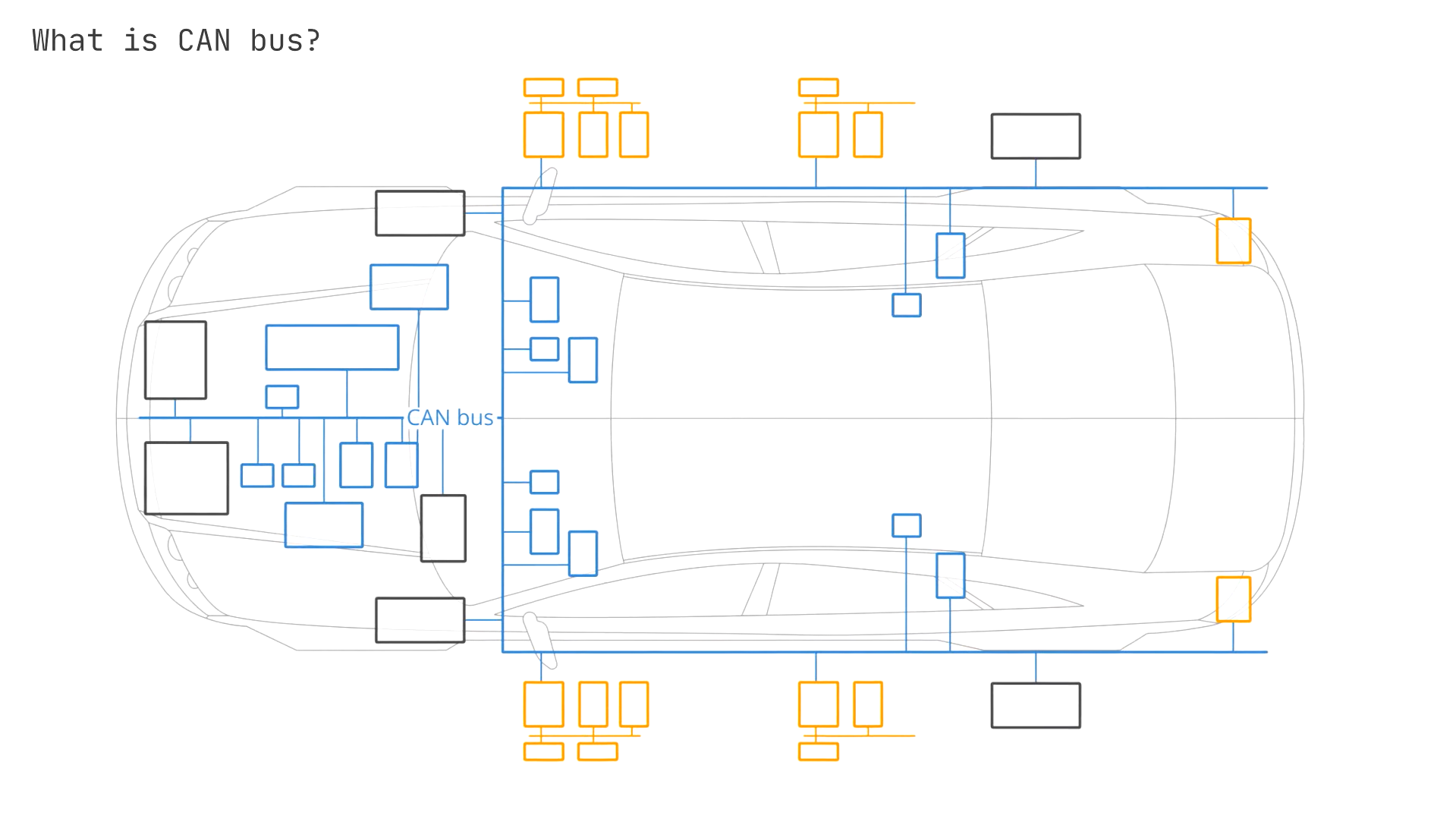
CAN bus stands for Controller Area Network Bus, a communication system that allows individual vehicle systems to log and report if they are functioning properly or not. It is a message-based protocol that allows Electronic Control Units (ECUs) to communicate with each other in a reliable, priority-driven manner.
The CAN bus is used primarily in automotive systems to establish interconnected communication between various Electronic Control Units (ECUs). These ECUs may include engine control units, transmission control modules, airbags, antilock braking systems, and more. The CAN network allows these components to exchange data and status information.
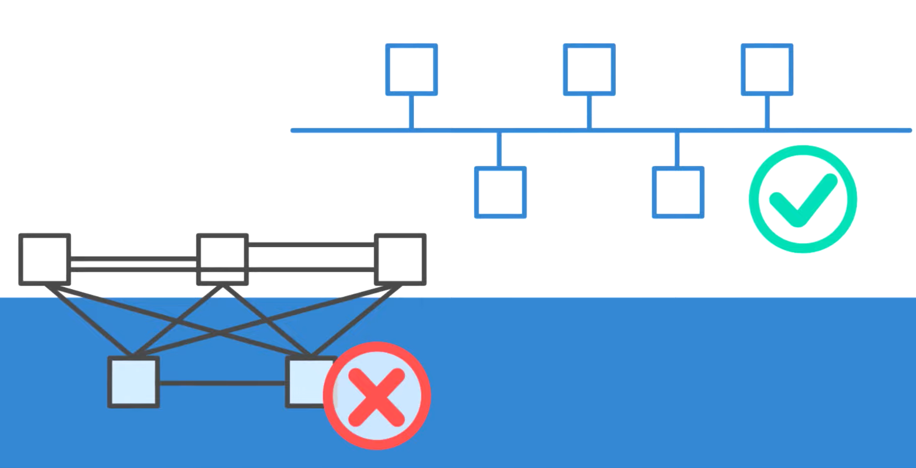
Message-Based Protocol: Unlike traditional point-to-point wiring systems, the CAN bus is a message-based protocol. This means that a single CAN bus line carries messages addressed to specific ECUs instead of having individual wires connecting each ECU. The ECUs act as different nodes on a central line. Such a design reduces wiring complexity and allows for more flexible system architectures. It especially aids in installing and removing additional components and makes modifications easier.
Reliable Communication: The CAN bus is designed to be highly reliable. It’s vital in automotive and industrial environments, where real-time action can often be the difference between safety and casualty. The bus communication system features built-in error detection mechanisms and the ability to resend transmitted data in case of transmission errors. So, even in electrically noisy environments or harsh conditions, the data stream remains accurate and consistent.
Priority-Driven: Each message on the CAN bus has an identifier that determines its priority. High-priority messages (such as those related to safety) can interrupt lower-priority messages. The protocol uses a priority-based system to manage message priority and ensures that critical information is transmitted without delay. Also, the large data payload combined with high-speed data transmission allows critical data to appear quickly and also other relevant data to travel without much delay.
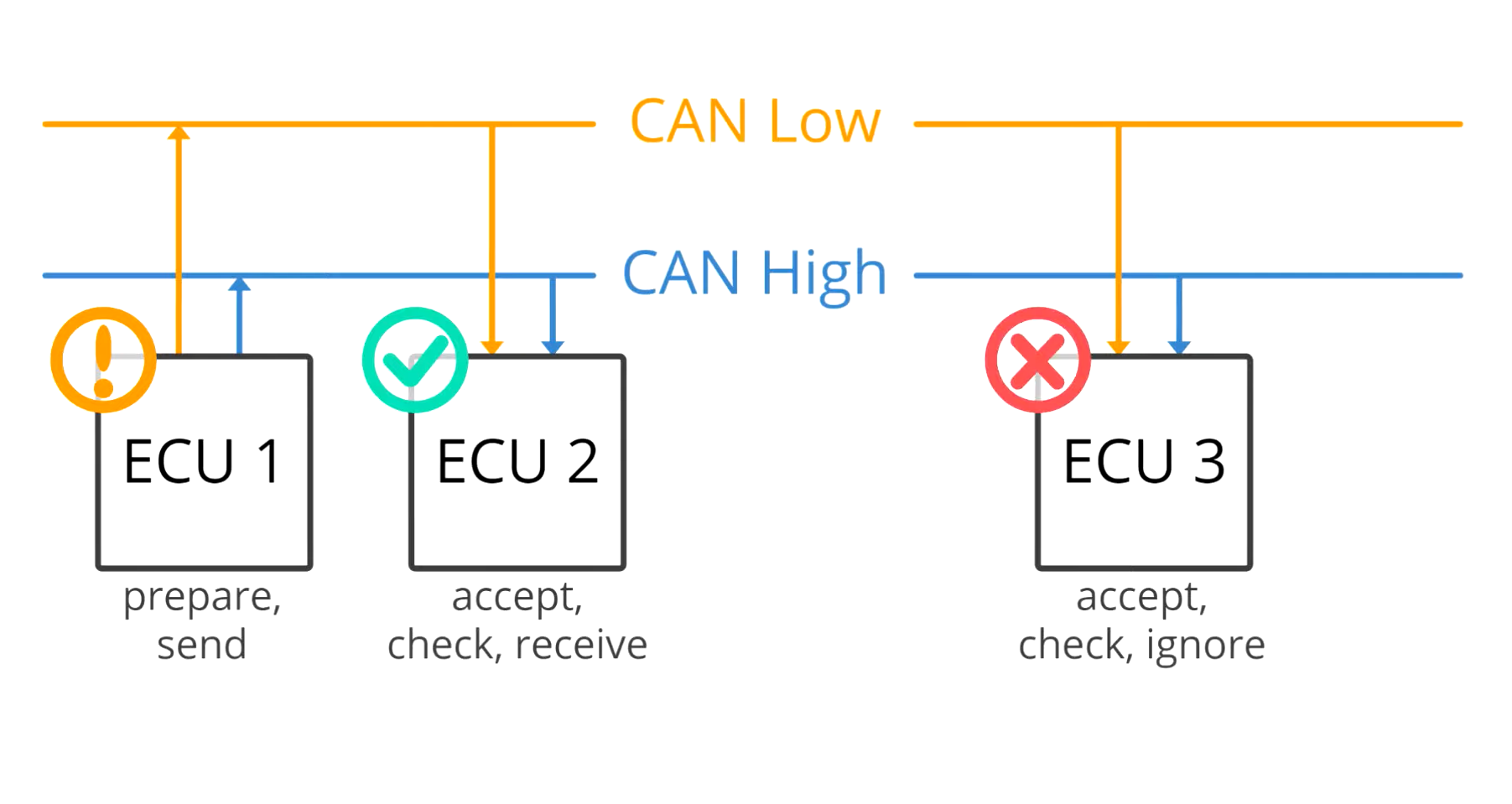
ECU Interaction: ECUs communicate with each other over the CAN bus by broadcasting their messages. Each ECU can listen to the bus and decide whether the message is relevant to its functions. This makes real-time data exchange and coordination possible between different vehicles. It also ensures data integrity for bus systems. You can adjust engine performance based on transmission data or activate safety features when needed.
Scalability and Flexibility: The CAN bus system is highly scalable. It supports a wide range of devices and applications. You can use it in simple systems with a few ECUs or in complex networks with dozens of interconnected devices. Not only does the system ensure efficient communication between multiple devices, but such flexibility also makes it suitable for automotive applications as well as industrial automation, medical equipment, and other fields requiring reliable, actual data.
CAN Bus Applications:
Automotive: In vehicles, the CAN bus enables the integration and coordination of systems such as engine management, transmission, braking, and lighting. This integration enhances vehicle performance, safety, and fuel efficiency.
Industrial Automation: The CAN bus connects sensors, actuators, and control units in factory automation, providing efficient and reliable control over manufacturing processes.
Medical Equipment: CAN buses in medical devices allow real-time data exchange and coordination between different diagnostic and monitoring systems.
Brief history of CAN bus
The Controller Area Network (CAN) bus originated in the early 1980s. Robert Bosch, a German industrialist and engineer, attempted to simplify wiring and enhance data exchange between electronic control units (ECUs) for efficient and reliable vehicle communication systems.
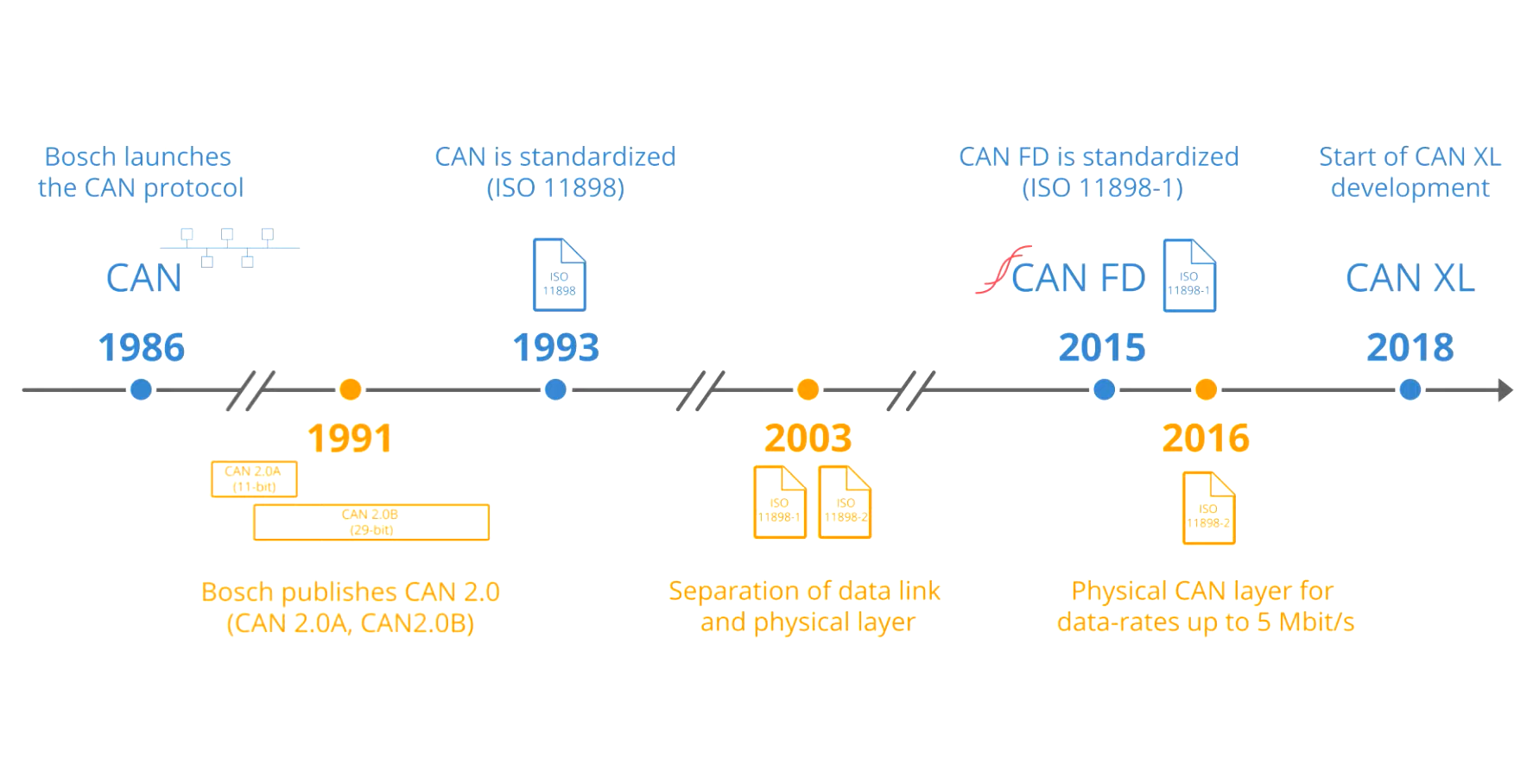
In 1987, the first CAN controller chips changed vehicle electronics by allowing multiple ECUs to communicate over a single bus. Also, the CAN bus standard, ISO 11898, officially published in 1989, set a benchmark for real-time and robust communication. This innovation laid the groundwork for its widespread use in automotive and industrial applications.
Since 2001, the European Union has mandated the On-Board Diagnostics (OBD)-II standard for all European vehicles running on petrol. This requirement came into effect for diesel vehicles in 2004. In the United States, all cars sold since 2008 must use the ISO 15765-4 signaling standard, a variant of the CAN bus.
How CAN Bus Works
CAN messaging and data message structure (CAN frame)
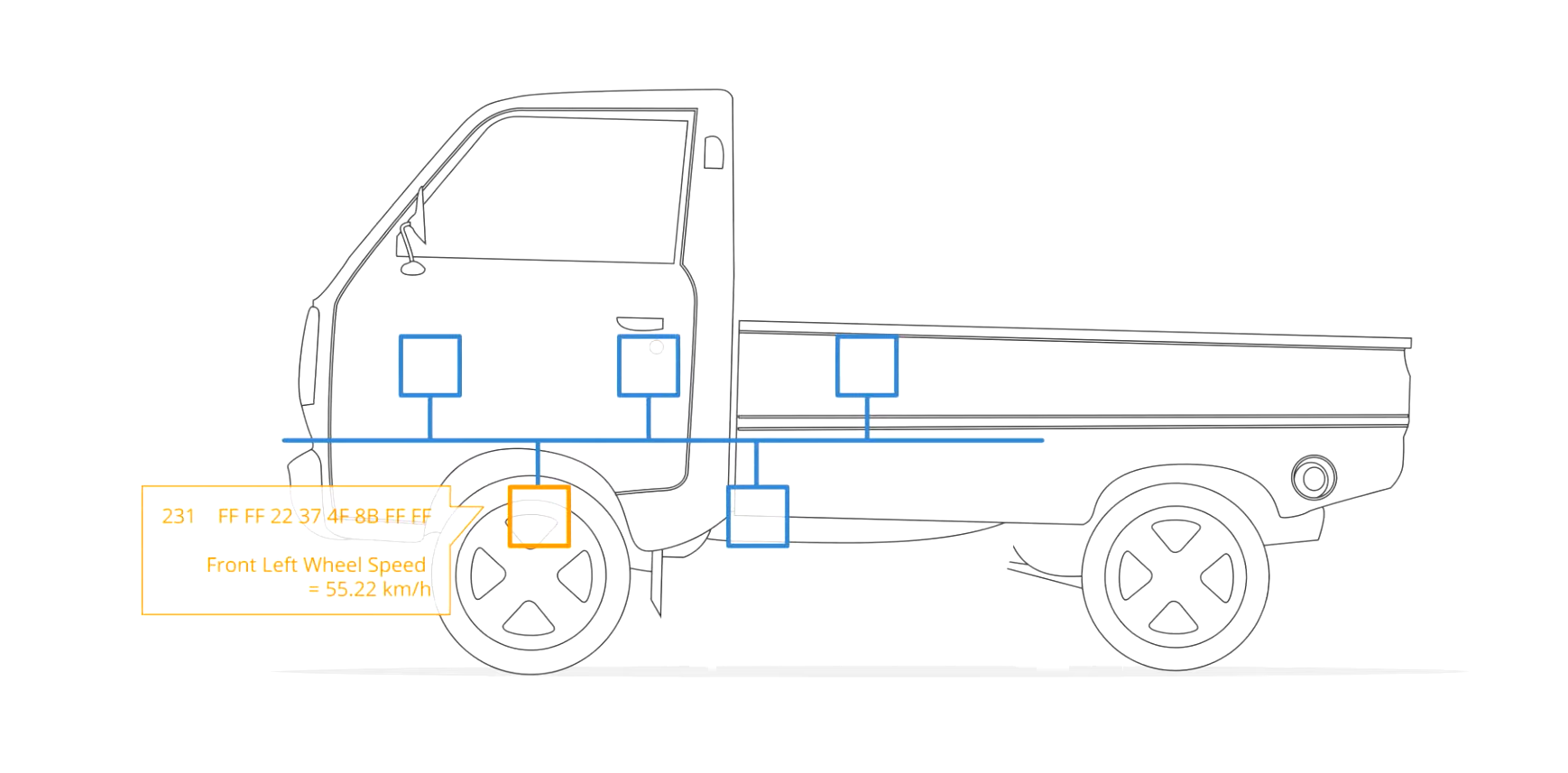
The bus system makes it easy for different Electronic Control Units (ECUs) in a vehicle to talk to each other through messages. This can be compared with the neural network on a human body which connects all the organisms. Each message on the CAN bus has an identifier that determines its importance, which helps prioritize what gets sent first.
When different components try to send messages at the same time from multiple nodes, CAN’s clever bitwise arbitration method makes sure that the most important message goes through first. This way, critical information gets through immediately. All the nodes on the CAN bus are synchronized, meaning they all read and process data together at the same time and use the network simultaneously. This synchronization helps the connected devices remain active and functional all the time.
Low-speed CAN and high-speed CAN variations
CAN bus technology comes in two main variations: Low-Speed CAN and High-Speed CAN.
Low-speed CAN: This variation operates at speeds up to 125 kbps and is typically used for non-critical systems such as body control modules, door locks, and window controls. It’s ideal for applications where data transmission speed is less important than the system’s cost-effectiveness.
Low-speed CAN also supports fault-tolerant operation. If a fault occurs on one of the lines, the system can continue to function using the remaining line. So, even if the task is less important, a CAN protocol is always reliable.
High-speed CAN: This data frame format, on the other hand, can reach speeds up to 1 Mbps. Such a high maximum data rate makes it suitable for more time-sensitive and critical systems like engine management, transmission control, and electronic braking systems. High-speed CAN is widely adopted in automotive applications where speed and integrity are paramount. Flexible data rates further ensure reliable communication between vital vehicle components.
Benefits of CAN Bus in Vehicles
Advantages of using CAN bus in vehicles
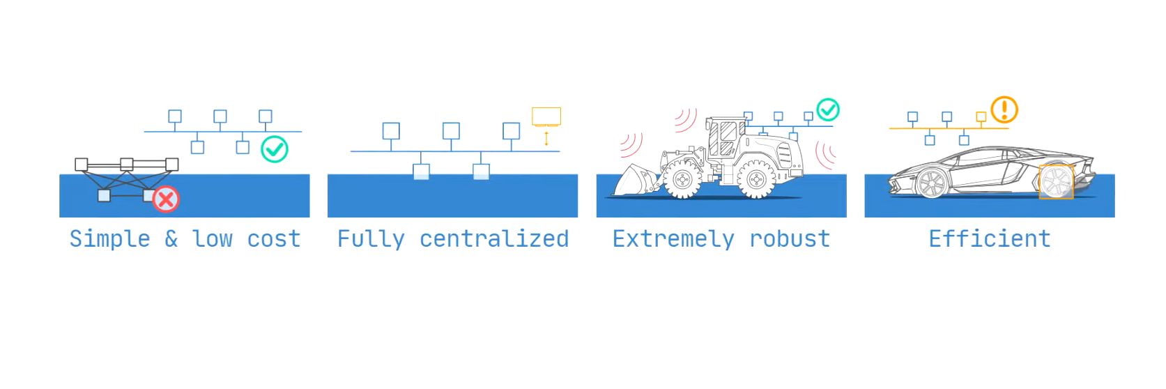
- Simple and low cost: ECUs communicate via a single CAN system instead of via direct complex analog signal lines. Lower wiring costs and easier system upgrades lead to reduced overall vehicle manufacturing and maintenance expenses.
- Fully centralized: The CAN bus provides one point of entry to communicate with all network ECUs. It enables centralized management of distributed electronic components to increase the overall system efficiency and coordination.
- Extremely robust: The system is robust towards electric disturbances and electromagnetic interference.
- Efficient: CAN frames are prioritized by ID numbers. This facilitates detailed monitoring and troubleshooting of vehicle systems through standardized messaging and status reporting.
- Reduced Wiring Complexity: Minimizes the need for extensive point-to-point wiring, simplifying vehicle design and reducing weight.
- High Reliability: Features built-in error detection and correction. Reliable data transmission even in harsh environments.
- Real-Time Communication: Supports rapid data exchange with minimal delay and allows for time-sensitive applications like engine control and safety systems. CAN systems provide valuable insights into ECU performance and the integrity of complex systems.
- Scalability: Easily integrates additional ECUs or sensors and supports the expansion of vehicle functionalities without significant redesigns.
- Fault Tolerance: Particularly in Low-Speed CAN, allows continued operation even if some components fail or if there are issues on one of the communication lines.
- Compatibility: Adheres to standardized communication protocols to boost interoperability across different manufacturers and systems.
- Enhanced Safety: Provides prioritized messaging to ensure vital data, such as braking and stability control, is transmitted without delay, contributing to vehicle safety.
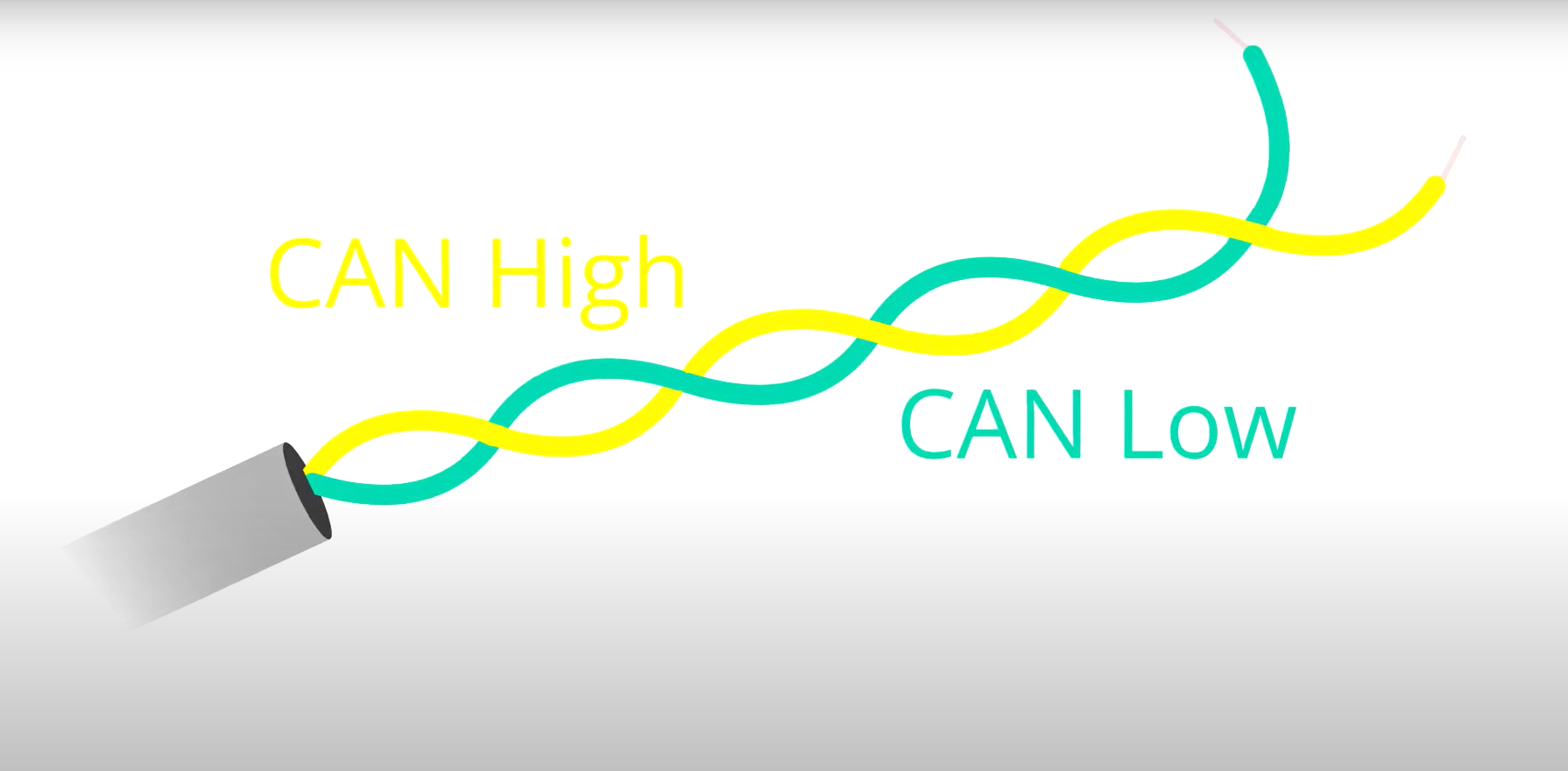
- Reduced Electromagnetic Interference (EMI): The differential signalling technique reduces susceptibility to external noise and EMI. This significantly reduces the error frame on complex systems.
- Futureproofing: Allows for easier updates and integration of new technologies, adapting to future advancements without overhauling the entire communication system.
Popular CAN bus applications in the automotive industry
Today, applications for CAN are dominated by the automotive and motor vehicle world, but they are not limited to that.
- Engine Management: CAN facilitates communication between the Engine Control Unit (ECU) and various sensors and actuators to optimize fuel injection, ignition timing, and emission control for improved performance.
- Transmission Control: The real-time coordination between the transmission system and other vehicle components permits smooth gear shifts and adapting to different driving conditions for improved drivability.
- Anti-lock Braking System (ABS): Communicates data between the ABS control module and wheel speed sensors to prevent wheel lock-up during braking.
- Infotainment Systems: CAN controls audio, navigation, and communication systems by forming a local interconnect network. This network allows each component to interact seamlessly with each other. Different ECUs operating on the same network provide a unified user experience and centralized control.
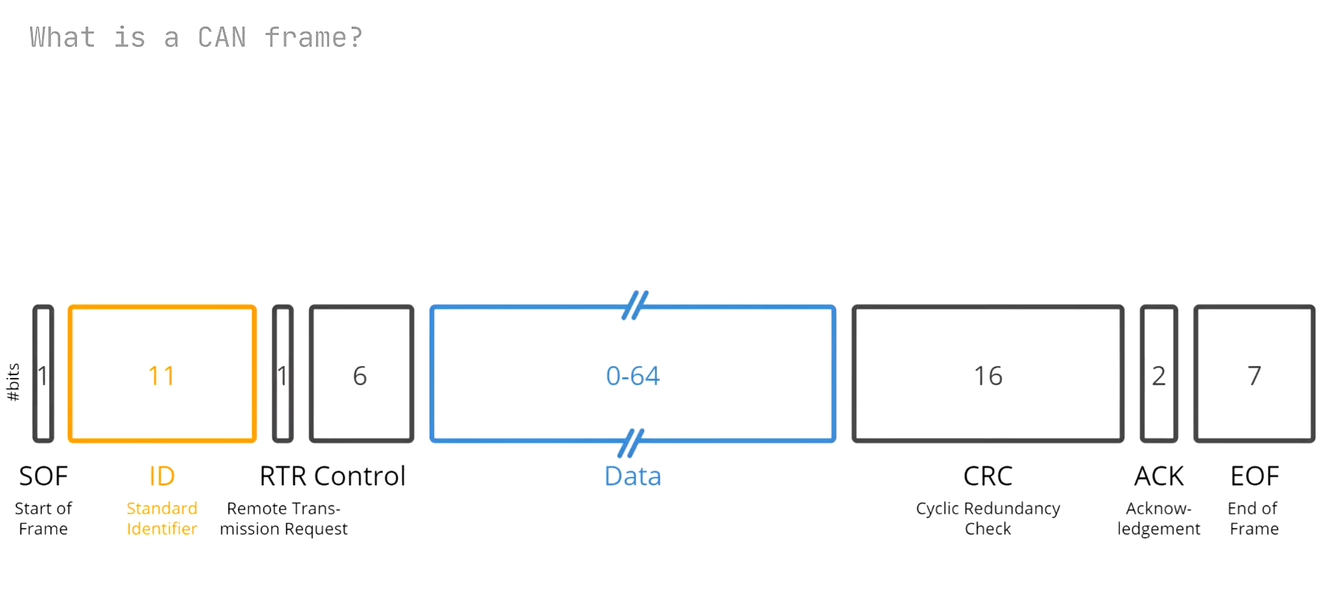
- Advanced Driver Assistance Systems (ADAS): Supports integrating systems like adaptive cruise control, lane-keeping assist, error detection, and collision avoidance by enabling rapid data exchange between sensors, cameras, and control units for real-time decision-making and safety interventions. CAN FD (Flexible Data Rate) protocol introduces fixed stuff bits in the CRC field for longer data frames (more than 8-byte payload). CAN DLC or data length code typically ranges from 0-8 bytes. The flexible data rate further makes CAN an evolving and synchronized system. To further ensure data integrity, a cyclic redundancy check is carried out.
CAN Bus System in LED Lighting
What are CAN Bus LED bulbs?
CAN bus LED bulbs are specialized for vehicles with a CAN bus electrical system. These ECUs for LEDs not only improve lighting performance but also enhance safety by providing real-time feedback and status indicators. Bus bulbs include built-in resistors/controllers to prevent issues like flickering, error messages, or malfunctioning lights that can occur when standard LEDs are installed in such systems. A CAN bus bulb greatly ensures proper integration with the vehicle’s lighting and electronic controls.
Choosing a CAN bus LED ECU means investing in a future-proof lighting system that brings the latest in digital control to your vehicle. It’ll simplify the installation for you and enable advanced diagnostics and custom lighting behaviors that you can synchronize with the vehicle’s operations.

Benefits of using CAN Bus LED bulbs in vehicles
- Eliminates “bulb-out” warnings on the dashboard so that the vehicle recognizes the bulb as functional.
- A can bus bulb is designed to fit directly into existing sockets without requiring additional modifications.
- Built-in resistors prevent flickering and provide stable, consistent lighting.
- Can bus bulbs work with the vehicle’s CAN bus system and avoid communication issues.
- A bus bulb consumes less power than traditional bulbs and noticeably reduces strain on the vehicle’s electrical system.
Non-CAN Bus LED Options
What are non-CAN Bus LED bulbs?
These LED automotive light bulbs lack the load resistors necessary to simulate the electrical load of traditional halogen bulbs. Unlike a bus bulb, they do not provide the additional resistance needed for compatibility with vehicles equipped with a CAN bus system. This absence of resistors can lead to various issues in CAN bus-equipped vehicles, such as dashboard error messages indicating bulb failures, flickering lights, or malfunctioning systems.
Non-CANbus bulbs can still offer the benefits of improved energy efficiency as well as brighter illumination. However, they are generally suited for non CAN bus applications where compatibility issues are not a concern.
What are bus stands
CAN bus stands (or CAN bus adapters) are devices or modules that integrate non-CAN bus bulbs or other electrical components into a CAN bus system. They typically include a load resistor or circuitry that mimics the electrical load of traditional bulbs. They must pose as such because mimicking the nature of bus bulbs prevents error codes, flickering, or malfunctioning when installing LEDs or aftermarket parts. This is necessary for smooth operation and compatibility with the vehicle’s CAN bus system.
Advantages and disadvantages of non-CAN Bus LED bulbs
Advantages:
- Generally cheaper than CAN-bus LED bulbs. A budget-friendly option for vehicle lighting upgrades.
- Simple plug-and-play installation with no need for a load resistor or other modifications.
- Consumes less power compared to traditional halogen bulbs, which in turn extends the life of the vehicle’s electrical components.
- Provides more intense and focused illumination for improved visibility.
Disadvantages:
- In CAN bus-equipped vehicles, they can trigger dashboard error messages indicating bulb failures.
- These may not work properly with vehicles that have CAN bus systems. Without dedicated bus stands, they can cause flickering or malfunctioning lights.
- The lack of proper load simulation might cause interference with other electronic systems in CAN bus-equipped vehicles.
- Lacks built-in features to communicate with the vehicle’s diagnostic systems. Limits the ability to monitor bulb performance and health.
- Depending on the region and vehicle, using non-CAN bus LEDs in CAN bus systems may violate vehicle warranties or fail to comply with regulations.
Key Differences Between CAN Bus and Non-CAN Bus LED
Bus systems: CAN bus system vs non-CAN bus system
- CAN bus system: A communication system that allows individual vehicle systems to report if they are functioning properly.
- Non-CAN bus system: A system that does not use CAN bus for communication.
Load resistor requirements
- CAN Bus LED bulbs: These have built-in resistors that simulate the load of the original halogen bulbs. They do not require additional components.
- Non-CAN Bus LED bulbs: May require additional load resistors to work properly in CAN Bus-equipped vehicles.
Cost
- CAN Bus LED Bulbs: These are typically more expensive due to the added components and technology for CAN bus integration.
- Non-CAN Bus LED Bulbs: More cost-effective. A budget-friendly choice for vehicles that do not require CAN bus compatibility.
Ease of Installation
- CAN Bus LED Bulbs: Plug-and-play design dedicated to CAN bus systems. No need for external resistors or additional wiring.
- Non-CAN Bus LED Bulbs: Easy to install as well in non-CAN environments but may require additional components or modifications to work correctly in CAN bus systems.
Performance and Reliability
- CAN Bus LED Bulbs: Provide stable performance with no flickering, accurate error reporting, and full compatibility with the vehicle’s diagnostics. Even if it’s only one node, the bus detects and reports any problem.
- Non-CAN Bus LED Bulbs: May generate issues like flickering or malfunctioning when used in CAN bus systems if there’s a lack of load simulation.
Hyper-flashing and “bulb-out” indication prevention
- CAN Bus LED bulbs: Designed to prevent “bulb-out” indications and hyper-flashing in CAN Bus-equipped vehicles.
- Non-CAN Bus LED bulbs: This may cause “bulb-out” indications and hyper-flashing in CAN Bus-equipped vehicles.
Choosing the Right LED Bulb for Your Vehicle
Determining if your vehicle has a CAN bus system
1. Consult Your Vehicle’s Owner’s Manual: First, you need to review the vehicle’s owner’s manual. This manual provides necessary information about your vehicle’s systems, including the lighting and electrical setups. Look for sections that discuss the vehicle’s electrical architecture or bulb replacement procedures. If your vehicle uses a CAN bus system, this information will often be explicitly stated. The manual might also indicate if specific bulbs or electronic components are designed to work with a CAN bus. You can also search the internet or consult with the manufacturer.
2. Remove a Light Bulb: If the owner’s manual does not provide clear information, you can manually test your vehicle. Begin by removing one of the light bulbs, such as a headlight or taillight. This process varies from vehicle to vehicle as the build and model are different for them. So please refer to the manual for removal instructions. You should also make sure the vehicle is off and parked securely before removing the bulb to avoid any electrical issues or injuries.
3. Observe the Vehicle’s Response: After removing the bulb, turn on your vehicle. Look at the dashboard for any warning messages or indicators that a bulb is out. In many CAN bus-equipped vehicles, the system monitors the status of light bulbs and will display a “bulb-out” warning if it detects a bulb has been removed or is defective. You may see the error message typically appear on the instrument cluster or central display. A CAN system actively monitors the bulbs. So, if there is no warning, your vehicle probably doesn’t have a bus system.
If you still have not managed to figure it out, simply consult a mechanic the next time you’re out for maintenance.
Factors to consider when selecting an LED bulb
- Vehicle type and make
- Lighting system type (CAN Bus or non-CAN Bus)
- Bulb type and wattage
- Load resistor requirements
- Socket and fitting compatibility
- Brightness and color temperature
- Heat dissipation
- Voltage compatibility
- Lifespan and durability
- Warranty and post-sale services
Installation and Troubleshooting
Connecting to CAN Bus
To connect the LED to the CAN bus system, follow the manufacturer’s instructions carefully. First, verify that the bulb is CAN bus compatible. Ensure proper alignment with the socket and secure the connections. Double-check the polarity, as LEDs are polarity-sensitive. If issues arise, consult the vehicle’s manual or seek professional assistance.
Decoding CAN Bus Data
To decode bus data transmitted on the CAN bus, use a CAN bus decoder or scanner. Connect the decoder to the OBD-II port or directly to the CAN bus network. You’ll be able to monitor and interpret communication between ECUs, diagnose issues, and ensure the LED is correctly integrated with the system. Follow decoder instructions for accurate data retrieval.
Common Issues and Solutions
- “Bulb-Out” Indications: Verify that the LED is compatible with the vehicle’s CAN bus system. If not, use a CAN bus bulb or an external load resistor to simulate the original bulb’s electrical load.
- Hyper-Flashing: Check if the LED has a built-in resistor. If hyper-flashing persists, install an additional load resistor to balance the circuit and ensure proper flashing rates.
Summary of key points
- CAN Bus is a communication system that allows individual vehicle systems to report if they are functioning properly.
- It’s a nervous system for vehicles that connects ECU nodes and handles the transmission of important data.
- CAN Bus LED bulbs are designed to prevent “bulb-out” indications and hyper-flashing in CAN Bus-equipped vehicles.
- Non-CAN Bus LED bulbs may cause “bulb-out” indications and hyper-flashing in CAN Bus-equipped vehicles.
- Proper load or simulated load is necessary for the system to work flawlessly. Also, a frame format ensures proper communication between the vehicle and the ECU.
Upgrade Your Fleet with Reliable CAN Bus LED Solutions
We encourage using CAN Bus LED bulbs in vehicles equipped with this system to avoid potential issues like “bulb-out” warnings and hyper-flashing. It’s also to preserve the overall integrity of your system. Try to avoid non-CAN bus bulbs unless you know what you’re doing.